
This is the major disadvantage of pass transistors. Oscillation circuit: Inverter (unbuffer). Hence when the pass transistor pulls a node to high logic the output only changes upto VDD–VTh.

As discussed NMOS devices are effective in passing strong '0' but it is poor at pulling a node to VDD. The another advantage of pass transistor logic is the lower capacitance because of reduced number of transistors. If we compare this with the same AND gate implementation using pass transistor logic the number of transistors required are four including the two transistor required to invert the input B. To illustrate this consider the implementation of AND gate using complementary CMOS logic. The major advantage of pass transistor logic is that fewer transistors are required to implement a given function.

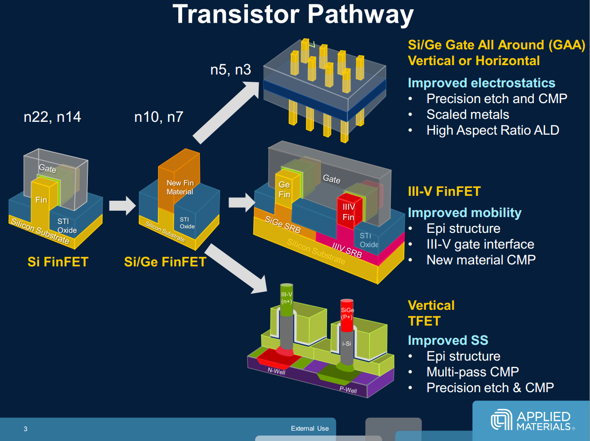
However, higher supply voltage implies increased power dissipation (CV2f). Since the transistor current is proportional to the gate overdrive (VG-VT), high performance demands have dictated the use of higher supply voltage. Capacitances in MOSFET - Scaling of MOS circuits - Review of CMOS. MOS Transistor 5 In reality constant field scaling has not been observed strictly. This satisfies the truth table of AND gate reproduced in Table below for verification. The MOS transistor- Current Voltage Relations- Threshold Voltage- Second order effects. There are two types of MOS transistors positive-MOS (pMOS) and negative-MOS (nMOS). In particular, they are constructed out of metal-oxide semiconductor (MOS) transistors. When B is low the right NMOS pass transistor is turned ON and passes a '0' to the output F. 31, 2022 Image: Shutterstock / Built In Microprocessors are built out of transistors. In this gate if the B input is high the left NMOS is turned ON and copies the input A to the output F. Jay Brockman, Joseph Nahas, University of Notre DameProf. In complementary CMOS logic primary inputs are allowed to drive only gate terminals.įigure below shows implementation of AND function using only NMOS pass transistors. Stick Diagrams:Euler Paths Peter Kogge University of Notre DameFall 2015, 2018 Based on material fromProf. As designers took advantage of scaling (1974 Milestone) to pack hundreds of thousands of transistors onto a chip, CMOS provided the best solution to manage the resulting power density issues.The Pass transistor logic is required to reduce the transistors for implementing logic by using the primary inputs to drive gate terminals, source and drain terminals. By 1978, when Toshiaki Masuhara of Hitachi described a high-speed RAM at ISSCC, the combination of smaller lithography with the silicon-gate process enabled CMOS to compete in performance with bipolar and conventional MOS.
Cmos transistor diagram portable#
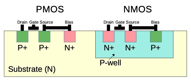
The first high-volume applications for CMOS circuits emerged in battery-operated consumer products such as digital watches (1974 Milestone) and portable instruments that did not demand the ultimate in speed. In any circuit, the output of a transistor. The four MOSFET symbols above show an additional terminal called the Substrate and is not normally used as either an input or an output connection but instead it is used for grounding the substrate. In a complementary transistor pair, one of the transistors is always turned on, while the other is turned off. Using a unique silicon-gate, closed-geometry CMOS process to minimize leakage, RCA's 1975 COSMAC 1802 microprocessor was the forerunner of millions of engine control processors built for Chrysler automobiles. The symbols and basic construction for both configurations of MOSFETs are shown below. from Boolean equations directly to the transistor level, skipping the logic gate level. In 1968 the company demonstrated a 288-bit static RAM and introduced the first members of the popular CD4000 family of general-purpose logic devices. In a large circuit, every CMOS is superseded and/or preceded by logic gates, which is again, nothing but a bunch of NMOS and PMOS transistors. Gerald Herzog led a major CMOS logic and memory circuit design program for an Air Force computer in 1965. RCA Research Laboratories and the Somerville manufacturing operation pioneered the production of CMOS technology (under the trade name COS/MOS) for very low-power integrated circuits, first in aerospace and later in commercial applications. Wanlass patented the idea that today is called CMOS. Note that there is no difference in the construction of a transistor source and a transistor drain.

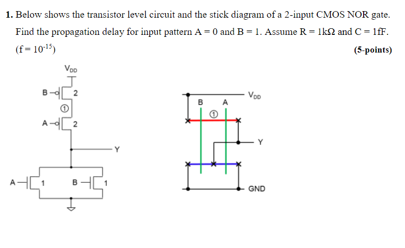
A transistor exists where a polysilicon stick crosses either an N diffusion stick (NMOS transistor) or a P diffusion stick (PMOS transistor). Sah and Frank Wanlass of the Fairchild R & D Laboratory showed that logic circuits combining p-channel and n-channel MOS transistors in a complementary symmetry circuit configuration drew close to zero power in standby mode. Mask Layout and Stick Diagram for a CMOS Inverter.


 0 kommentar(er)
